NEMA Wiring Schematic Manual for Electrical Experts
Approximately seventy percent of electrical malfunctions across facilities result from substandard wiring methods. This fact accentuates the need of following set guidelines, highlighting NEMA wiring diagrams’ value for electrical experts. Through these schematics, wiring configurations that fulfill both operational efficiency and highest security criteria are delineated.
The objective of this guide is to arm electrical professionals with profound knowledge into NEMA standards. Stressing the significance of proper electrical installations is crucial. Through mastering these guidelines, practitioners can drastically cut the likelihood of accidents and guarantee they comply with safety standards backed by Installation Parts Supply. Expertise in l14-30 plug wiring diagram is essential whether designing modern setups or repairing present ones, as it improves the ability to deliver safe and trustworthy electrical answers.
Principal Learnings
- NEMA wiring diagrams are essential for ensuring electrical protection and conformity.
- Proper wiring practices can minimize electrical malfunctions substantially.
- Comprehending NEMA standards boosts the performance of electrical arrangements.
- Installation Parts Supply encourages compliance with safety protocols in electrical work.
- NEMA diagrams accommodate a wide range of uses across multiple sectors.
Comprehending NEMA Criteria and Their Significance
NEMA criteria are crucial in the electrical field, directing safety and functionality precisely. Crafted by the National Electrical Manufacturers Association, they define key criteria for designing, evaluating, and marking electrical gear. It ensures standardization and dependability across all electrical set-ups, which is invaluable.
What Are NEMA Criteria?
NEMA classifications span from grades 1 through 13. Every level defines the conditions suitable for electrical apparatus to function optimally. For example, NEMA 1 delivers basic indoor security but is missing dust shielding. Alternatively, NEMA 4 guarantees appliances is sealed, a must for surviving substantial water immersion. Comprehending these categories is key in choosing appropriate appliances.
How NEMA Norms Matter for Electrical Protection
The impact of NEMA criteria in guaranteeing electrical security is significant. They play a significant part in reducing electrocution risks, device failures, and burn risks. Accurate adherence to NEMA classifications allows devices to perform safely under particular ambient conditions. For open-air application, NEMA 3 ratings offer protection against the elements, shielding the device from harsh climate like downpour and blizzard conditions. In areas at risk of explosions, ratings like NEMA 7, 8, and 9 are vital for ensuring security.
Applications of NEMA Criteria in Wiring Drawings
The use of NEMA criteria in wiring drawings is vital for secure, effective electrical installations. These schematics make use of uniform symbols and formats based on NEMA standards, streamlining the comprehension of detailed electrical arrangements. This uniformity is advantageous. It encourages transparency, uniformity, and minimizes errors, and thereby boosting electrical safety across home and factory sectors.
NEMA Wiring Diagram Essentials
NEMA wiring schematics are crucial for electrical professionals, ensuring complex connections transparent. They detail the junctions and parts in different configurations. By comprehending the parts, types, and notations of NEMA diagrams, electricians can enhance their operations in installations and servicing.
Constituents of NEMA Wiring Schematics
NEMA schematics comprise crucial elements for specific electrical setups. You’ll discover wiring terminals, connectors, and various fixtures for secure junctions. Every piece ensures power is distributed efficiently, in accordance with security standards.
Varieties of NEMA Wiring Schematics
NEMA utilizes different schematics, like linkage diagrams and circuit layouts. Schematics depict appliance associations, while layouts illustrate current flow. Choosing the appropriate drawing helps with troubleshooting and installation.
Typical Symbols Found in NEMA Wiring Drawings
Icons in wiring drawings are essential for clear communication. They depict switches, networks, and connectors. Understanding these icons helps crews read schematics correctly. Thus, it guarantees setups adhere to NEMA standards.
NEMA Wiring Schematic Features
For electrical professionals, grasping the fundamental elements of accurate electrical wiring drawings is vital. These schematics provide both clarity and wholeness, matching installations with NEMA standards. They require precise labeling and sizing to minimize setup mistakes. This fosters a protected and highly efficient workplace.
Key Features of Accurate Electrical Wiring Schematics
Precise electrical wiring drawings are indispensable in electrical initiatives. They encompass important qualities such as:
- Transparency: Diagrams are required to be simple, lowering the risk of misinterpretation.
- Thoroughness: They need to contain all essential elements, junctions, and electrical ratings.
- Standard Compliance: Complying with NEMA standards is imperative for securing security and operation.
- Thorough Annotation: Distinct labels on each part are essential for comprehension and avoiding mistakes.
- Proper Sizing: The scales should mirror the actual setup to portray the arrangement precisely.
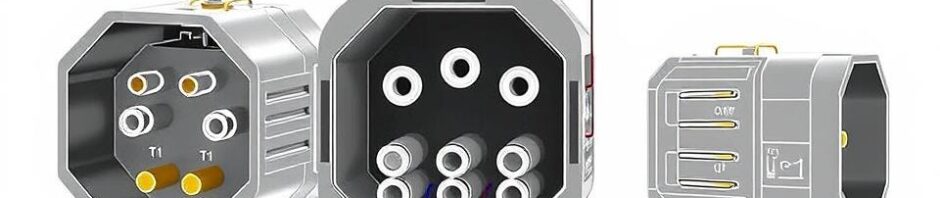
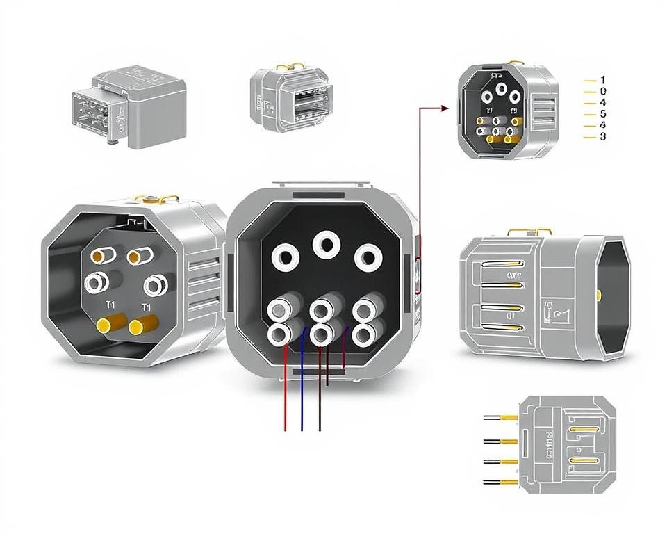
Understanding NEMA Connector Layout
The insight into NEMA connector layout is vital for forming proper linkages in electrical setups. Awareness of specific pin arrangements maintains protection and device operation. There is a diversity of NEMA couplers, crafted for distinct power levels and currents, including:
| Connector Model | Amperage Rating | Voltage Level |
|---|---|---|
| L5-15 | 15A | 125V |
| L5-20 | 20A | 125V |
| L14-20 | 20A | 125/250V |
| L1430C | 30A | 125/250V |
| L620C | 20A | 250V |
| L1430C | 30A | 125/250V |
| L630R | 30A | 250V |
Understanding NEMA coupler pinouts is vital for stable junctions, boosting performance. It’s paramount to align connectors with appliances correctly using locking or flat blade variants, to prevent dangers.
NEMA Appliance Wiring
NEMA appliance wiring covers various arrangements for protected electrical appliance interfaces. These guidelines confirm that appliances integrate reliably, minimizing danger. Knowing the various NEMA equipment and their wiring is vital for specialists.
Different Types of NEMA Appliances
NEMA classifies units by category based on power levels and current demands. Primary arrangements are:
- 2-Pole 2-Wire
- 2-Pole 3-Wire Grounding
- 3-Pole, 3-Wire
- 3-Pole, 4-Wire with Grounding
- 4-Pole, 4-Wire
- 4-Pole, 5-Wire with Grounding
These setups find use in homes and manufacturing plants, supporting 125V, 208V, and 480V.
NEMA Plug Wiring Demystified
NEMA plug wiring differs to meet various power needs, with rotary-lock types providing consistent interfaces in shaky conditions. For instance, the L5-15 plug is rated for 15 amps, frequently used in commercial locations, whereas the L14-20 is crafted for 20 A at 125/250 voltage.
The NEMA designation system helps in selecting the right plugs, emphasizing characteristics like charge orientation and earthing. Such accuracy secures that equipment perform reliably.
NEMA Outlet Wiring Guidelines
Accurate wiring of NEMA receptacles conforms to electrical standards and security protocols. For instance, L530R receptacles should be wired for 30 A at 125 V, with L630R models for 250 V. Correct grounding is vital to avoid electrical mishaps.
Opting for accredited NEMA plugs and receptacles guarantees secure, standard-compliant setups. It’s critical to refer to formal guidelines when setting up.
NEMA Motor Wiring and Applications
NEMA motor wiring is crucial in electrical engineering, especially for commercial use. Knowing how NEMA motor arrangement works guarantees that machines are integrated for peak operation. Such devices, like one-phase and tri-phase types, need proper wiring to work safely and efficiently.
Summary of NEMA Motor Wiring
Understanding NEMA motor wiring necessitates knowledge of junctions and setups. Most three-phase motors now support dual-voltage, meaning they can run on both low (208-230V) and high voltage levels (460V). High voltage wiring results in lower current draw than at low voltage. High voltage perks encompass reduced gauge wiring for the power feed, a major benefit for motors exceeding 10 HP.
While both NEMA and IEC appliances are employed in the market, NEMA variants are generally bigger and more expensive than IEC ones for under 100 HP applications. NEMA controllers vary from size 00 to 9, fit for various applications. A standard feature in NEMA controllers is a Trip Class of 20, designed to activate when a motor’s draw goes beyond 6x the Full Load Amperage in 10 seconds.
Opting for the Right NEMA Motor Configuration
Selecting the right NEMA motor configuration affects system operation and protection. A standard three-wire control circuit employs three wires for a start/stop pushbutton station, enabling direct motor operation. Common three-phase configurations comprise the 12 Lead Dual Voltage and 6 Lead, enabling Wye and Delta configurations.
IEC motor starters often include phase loss detection, enhancing safety. They also feature configurable Fault Classes for tailored protection in low power operations. Furthermore, many units have temperature safeguards, essential for single-phase and Dual Voltage setups.
| Configuration Type | Voltage Level | Amperage | Usual Function |
|---|---|---|---|
| 12 Lead Dual Voltage | Dual Voltage (208-230V / 460V) | Motor size dependent | Wye Start and Delta Run setups |
| 6 Lead | Single/Dual Voltage | 32 amps maximum | Wye/Delta configurations |
| Single Phase | One Voltage | Ranges from 1 to 5 amps | Dual Speed and Dual Winding setups |
| Delta Connection | Elevated Voltage | Depending on setup | Used for Current Transformers and various setups |
Final Thoughts
Understanding NEMA wiring diagrams and standards is crucial for electrical specialists aiming to boost their capabilities and follow electrical safety standards. These principles guarantee protected and high-performing electrical installations but also avoid hazards linked to improper wiring. As discussed, following NEMA norms yields the improved functionality of diverse NEMA appliances and systems.
For electrical professionals, the choice of quality materials can significantly impact the success of their tasks. Installation Parts Supply offers a extensive array of wiring supplies aligned with NEMA criteria. This allows specialists to get critical components for fulfilling these significant regulations. High-quality resources and deep understanding of NEMA wiring drawings substantially improve system protection and effectiveness.
During electrical setups, always place security and exactness first. Mastering NEMA norms offers the understanding needed for executing industry standards correctly. This guarantees that every electrical link made meets superior criteria.
FAQ
Which are NEMA wiring schematics?
NEMA wiring schematics illustrate the arrangements and junctions of NEMA-standard electrical gadgets. They comply with safety and performance norms defined by the National Electrical Manufacturers Association.
Why are NEMA standards important for electrical protection?
NEMA criteria are fundamental to establishing safety and functional criteria for electrical devices. These standards enable electrical specialists reduce electrocution risks, device malfunctions, and fire hazards.
What components are vital in a NEMA wiring drawing?
Fundamental parts in a NEMA wiring schematic include circuit configurations and junction blueprints. These diagrams also offer detailed labels and illustrate the electrical system’s different parts correctly for setups.
Which kinds of NEMA wiring schematics are used?
Diverse NEMA wiring drawings serve various requirements, including power distribution circuits and connector schematics. Every design serves a unique role in electrical setups.
Identify the common symbols employed in NEMA wiring drawings?
Common symbols in these drawings represent switches, fuses, outlets, and more. Use of these symbols promotes effective communication and accurate understanding of wiring drawings.
Identify the essential attributes of precise electrical wiring drawings?
Accuracy in electrical wiring drawings is characterized by their clarity, thoroughness, and clear annotation. They should conform to NEMA norms to avoid faults in installation.
Explain a NEMA connector pinout?
A NEMA connector pinout outlines electrical connections at a connector, showing distinct pin assignments. This secures secure and efficient connections in electrical systems.
Identify the different kinds of NEMA units?
NEMA appliances include various electrical sockets and interfaces, like adapters and receptacles. They are engineered for different current and power specifications to satisfy particular application requirements.
In what way is NEMA plug wiring configured?
NEMA plug wiring is determined by particular ampere and voltage levels needs, adhering to safety standards and regulatory standards for diverse electrical applications.
Identify the recommendations are there for NEMA receptacle wiring?
Recommendations for installing NEMA receptacles stress following electrical regulations, securing proper electrical polarity, and selecting proper wire sizes. This sustains both protection and performance in electrical installations.
What is the method to wire a NEMA motor efficiently?
To wire a NEMA motor, one must understand its specific single-phase or tri-phase arrangement. Choosing the right wiring approach is essential, along with maintaining electrical security for optimized motor performance.
What must be taken into account when choosing a NEMA motor setup?
Selecting a NEMA motor arrangement demands an evaluation of the project’s voltage and current demands and performance traits. It’s also crucial to ensure suitability with current machinery for guaranteed performance and safety.